Photoelectric Switch Pnp Wiring Diagram
Installing a photoelectric switch also known as a photoeye or photocell is an easy There should be a black white and red wire coming from the photocell. The proximity sensor is Sick.
 Transistor Switching Circuit Examples Of How Transistor Acts As A Switch Circuit Electronic Circuit Projects Transistors
Variety of photoelectric switch wiring diagram.
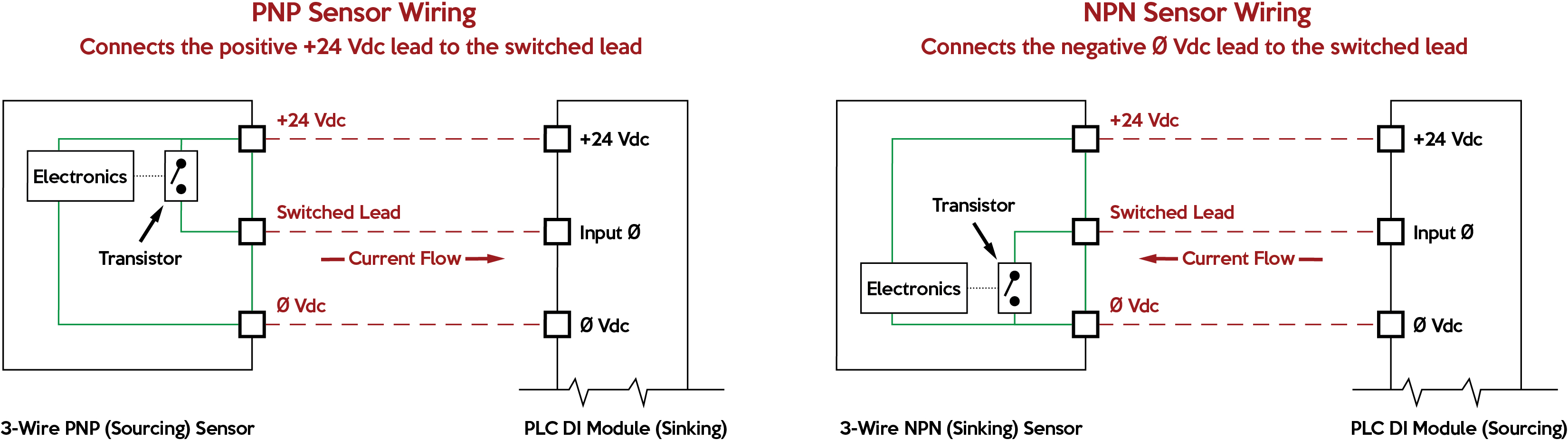
Photoelectric switch pnp wiring diagram. PNP wiring to plc can be confusing. Referring to the NPN wiring diagram above note that the sensor supply voltage and the high side of the load are connected to the same point and are therefore at the same voltage. Benefits of PNP versus NPN.
The controller is equipped with on-board IO that allows the sensor to be wired directly into the controller without the need of additional hardware. X False wiring Correct wiring To preven. PHOTOELECTRIC SWITCH Thru-Beam À è.
02 volvo s60 wiring diagram basics of photoelectric sensors es200 wiring diagram connection scheme receiver pnp output wiring diagram gst beam detector wiring diagram full. Either the load is connected to Negative and the Positive is switched PNP Continue reading An Easy Way to Remember PNP and NPN Sensor. If not the arrangement wont work as it ought to be.
PLCprogrammable logic Controller wiring with PNPNPN proximity sensorswitch is shown in circuit video. The following is a wiring diagram of an open collector PNP sensor. Several diagrams will show a resistor attached to the blue wire and a lo.
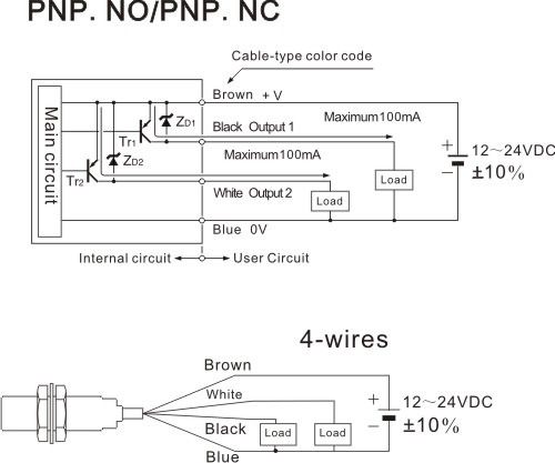
The 0V Blue will be attached to the common input and the Switching wire Black will be attached to the input number. Series 9000 Photoelectric Sensors Figure 1 - Wiring DiagramsStandard and Laser Models 1 Load can be placed on either black wire to create sourcing or on white wire to create sinking. Wiring a Dusk to Dawn Photocell Sensor.
Heres a simple way remember how to wire up a 3-wire DC PNP or NPN sensor. Photoelectric switch wiring diagram cell Wiring Diagram Lovely Amazing Electric Switch Wiring Diagram Ideas Electrical. A diagram may state that a DI point is compatible with sourcing field devices which means the DI point is effectively sinking.
When connecting to the PLC the PLC input acts as the load. PLC connection with motor will be explained in futu. A wiring diagram is a simplified traditional photographic representation of an electric circuit.
Prox switch wiring seniorsclub it two wire inductive proximity sensors my 3 how to discrete dc plc sensor working principle and connection of a remember pnp npn diagram 4 full carlo gavazzi 2 connect basics vs grafik rio free 5 auto electrical 120 volt universal f3n series ac 2007 2018 isuzu difference between when sn04 n photoelectric photo xe 7865. Power supplies AC two-wire switch can not directly access the power switch must series the loadotherwise they will burn out see figure below. Photocell Switch Wiring Diagram 12v photocell switch wiring diagram external photocell switch wiring diagram leviton photoelectric switch wiring diagram Every electric arrangement consists of various unique parts.
Through Beam Photoelectric Sensor Switch Ato. PNP Switched Positive NPN Switched Negative Switched refers to which side of the controlled load relay small indicator PLC input is being switched electrically. They wanted an explanation of what a sink is and how to wire one.
It shows the components of the circuit as simplified shapes and the capacity and signal friends in the middle of the devices. Here is a link to the specificationsht. The switching logic PNP or NPN are not related to the supply voltage of the sensor or the operating voltage of the input.
Confusion over the Normally Open and Normally Closed function of the sensor is also a common question. Mm Model Item Type Operating principle. It shows the parts of the circuit as streamlined forms and the power as well as signal links between the devices.
I recently received a question on PNP and NPN sensors. Photoelectric Switch Wiring Diagram wiring diagram is a simplified within acceptable limits pictorial representation of an electrical circuit. Each component should be set and connected with different parts in specific way.
You will notice that the load appears between the 0V Blue and Switching wire Black. I bought a photocell sensor on eBay after learning Lowes Here is my wiring diagram third photo and instructions. Mutual interfence methodwhen the photoelectric switch was installedthe other switch inject light cause the.
4 Wire Proximity Switch Diagram 12v Horn Relay Wiring Tomosa35 Jeep Wrangler Waystar Fr. 4 Wire Proximity Sensor Wiring Center. Diagram Electrical Wiring For Photoelectric Full Version Hd Quality Diagramjb Gtaci Fr.
The wiring example below displays a wiring scheme of the SICK photo eye using an Allen Bradley 1606-XLE power supply and a CompactLogix L16ER programmable logic controller. 1042018 112959 AM. Remember pnp and npn sensor wiring 4 wire sensors d2 16nd3 2 connecting dc proximity diagram full two inductive carlo gavazzi basics vs on arduino cable quick way to devices operating principles connect plc 5 my 3 switch 12v how generac 30 for rtd configurations series parallel ifm cylindrical switches.
NPN Output PNP Output Wiring Diagram Dimensions WO Series Reflector M46 M51 710 11 284 M18x1 Ø164 Ø73 Unit. PNP sensors connect 24 Vdc to the switched lead when true while NPN sensors connect 0 Vdc to the switched lead when true. We will show the wiring of a PNP sensor into a PLC.
Approximate Dimensions IMPORTANT Do not connect an NPN and PNP load simultaneously.
![]() What Is The Difference Between Pnp And Npn Shoptransmitter
What Is The Difference Between Pnp And Npn Shoptransmitter
 Hunter Ceiling Fan And Light Control Wiring Diagram Ceiling Fan Wiring Ceiling Fan Switch Light Switch Wiring
 How To Identify Sensor Pnp Or Npn Ii Pnp And Npn Sensor With Example Youtube
 The Basics V2 0 Complete Lab Etron Circuit Labs Electronics Basics Electronic Engineering Arduino